29.8.2022 - 19.9.2022 (Week 1 - Week 4)
Chung Yi Ki / 0345014 / BDCM
3D
Modeling
Exercises
Quick links
Lecture
Week 2 / Introduction to 3D Modeling
Blender user interface
Top to bottom:
-Top bar (menu, workspace, scene and layout)
- Area (area under workspace)
- status bar
Editor: Area where user edit the object
Outliner: Work similar with layers
Properties: Show property option for the objects
Timeline: Used to playback and keyframe animation
You can change the workspace name by double clicking the workspace tab.
Workspace name can be changed as well by first selecting preset and renaming
it.
To split window: hover to the corner of the screen until a “target” icon
appear and drag the window to the side to split
To rejoin window: drag from the corner of the window until an arrow icon
appears, and then drag to the window that you want to rejoin to
To change modes of editor: click the button beside “object mode”
View axis
In blender, the Z axis is the one that controls the height, this is called
z-up system. y axis controls back and forth, x axis controls left and right.
In the 3d view axis, the circles with fill colours are positive values, the
ones with outlines and lowered opacity circles are negative values.
Note: Front view of object is at -y value
To rotate the viewport, can click, hold, and drag the middle mouse button.
To track view (pan), hold down shift and click middle mouse button to drag.
To zoom in and zoom out, scroll middle mouse button. To have smooth zoom,
hold down ctrl and click, drag middle mouse button.
3d viewport

|
| Fig 1.1 Interface of 3D viewport |
There are two types of view angles in blender: perspective and
orthographic
Orthographic view: top, front, side, no vanishing point
Perspective view: has depth or vanishing point
Quad view fills the viewport with 4 windows showing different angles (top,
front, right orthographic and user perspective). To open quad view, press
ctrl + alt + Q on keyboard.
Viewport toolbar
From top to bottom: zoom, track (pan), camera, orthographic view
Maximize/minimize orthographic view
To open property shelf, press N on the keyboard or drag the little arrow
beside the view axis control. After that go to quad view > uncheck lock
rotation > mouse over to any of the 4 windows and press ctrl+alt+Q to
maximize each of the windows in quad view. Note that quad view option will
only show up when quad view is open.
Object selection: left mouse button > click on object to select the
object
De-select object: left mouse button > click anywhere on the 3d viewport
except the object
Multiple selection: hold shift + left mouse button and click on any object
De-select object in multiple selection: hold shift + left mouse button click
on the object (may need to double click at certain times)
In class activity
After Mr. Kamal gave us a lecture on the interface of Blender, we followed
along Mr Kamal’s demonstration of modelling simple 3D objects. We modeled a
snowman and a table with fruits using simple shapes.

|
| Fig 1.2 Snowman 3D model |
The snowman body is made up of spheres, its hat and hands are made up of
cylinders and its nose is made up of a cone. The shapes are deformed from
its default look using the transform tool. For example, the hat is a
cylinder scaled down and up, same goes to the hands but with rotation for
the fingers. The sphere is later applied shade smooth to smoothen out the
default edges.

|
| Fig 1.3 Table with fruits 3D model |
The table is made up of cylinders with their scale adjusted, same goes to
the fruit plate. The fruits are made of different sizes of spheres.
Week 3 / Rendering and Non-Destructive Polygonal Modeling
Viewport shading and rendering
The default render engine in blender uses Open GL, the same as workbench.
It carries out viewport rendering, or in other words, what you see in the
viewport is what you get when you render. Another render engine is Eevee
which carries out real time rendering. The third render engine is Cycles
which is
CPU based rendering.
Steps on assigning material to objects
- Select the object
- Click material properties in the property editor (the 2nd last button)
- Click new to create new material
Viewport display settings in material assignment menu
Color - changes color
metallic - adjust the metallic appearance of the object from a scale of 0
to 1
Roughness - adjust the shine of the object from a scale of 0 to 1, 1
indicated non-shiny
material
Assigning the same material to different object
Method 1
Previous created material can be assigned directly to different object by
clicking the icon
next to new (aka: material library) Material name can be changed by
double
clicking it in the material window
Method 2
Material can be linked from one object to another by first pressing the
object that
you want to assign material, next press the object which has the material
you want,
press ctrl+L on keyboard and select link material
Changing the camera angle and frame in camera view
View the object in camera view by pressing the camera button in the
viewport toolbox or
by pressing "0" on the numpad of your keyboard. Then, press "N" to bring
up properties shelf, after that go to view lock and check camera to view.
Uncheck it after you're happy with the view and don't want to change it.
To set the size resolution, go to properties editor > output properties
(3rd button). We can also choose a preset by clicking the list icon button
beside format.
To display the rule of third line in the viewport, first select the
camera. Then, select object data properties (the camera icon in the
property editor) and go to viewport display > composition guide, check
third.
Shading and rending look setting
In the shading options, click the down arrow button to access the shading
settings. Make the viewport is in solid mode before doing this.
Lighting settings
Studio - Default setting that controls lighting with applied
materials
Matcap - provides preset materials to choose
Flat - gives a flat appearance
Shading settings
Click material under color to view color from the applied materials.
Check shadow under option to add shadows. To customize the shadow, click
the cog icon beside
it. Click and rotate the sphere to change the shadow direction. Shadow
shift adjust the coverage of the shadow and shadow foc asjust the shadow
blending to look soft or sharp.
Final output rendering
First, disable show overlay to hide all display except the model. Then, go
to view > viewport rendering to render the final image.
In class activity
While presenting the lecture, Mr. Kamal demonstrated how to assign
material and render a scene in Blender by using the snowman model that we
made in week 2 class. We follow along the demonstration using our snowman
file.

|
| Fig 2.1 Snowman viewport display |

|
| Fig 2.2 Rendered snowman scene in studio lighting |
Non-destructive polygonal modeling
Apply simple deform modifier
Before applying simple deform modifier, the object needs to be subdivided
for the modifier
to work the right way. To apply a modifier, click the modifier properties,
which is the spanner icon, in the properties editor.
When applying subdivision surface, choose the simple option and set the
subdivision level viewport to the desired number (usually 2 or 3).
Subdivision modifier should be applied before simple deform modifier
To view the object wireframe at viewport display, make sure overlay is
turned on and click the drop down button and check wireframe under
geometry. Optimal display should be turned off in the subdivision modifier
too to see the wireframe of the subdivided geometry.
To apply simple modifier, select the object, go to properties editor >
modifier properties > add modifier > deform > simple
deform.
Four settings in simple deform: twist, bend, taper, stretch
Week 4 / Continuation of polygonal modeling - non destructive
method
Array Modifier
Used to create a series of duplicated objects along a path. In the
settings of the modifier, choose fixed count in fit type and in the
count box, key in the number of duplication.
Plain axes can be added as a point to set origin for simple deformation.
So, direction of deformation
can be changed by changing the direction of the object.
When using simple modifiers, first apply the subdivision surface
modifier to an object and apply the chosen simple modifier.
Problem with using bend in simple deform for plane
Bend would only work on z-axis, x and y axis will have no influence on a
subdivided plane. To solve this, first rotate the plane up to 90 degrees
on the axis, facing the front side. Second, apply all transformation by
selecting the object and go to viewport menu > object >
apply > all transform
Using array along a curve
First apply array modifier on the object, set the count number. Then,
apply the curve modifier and select the curve you want the deformation
to be based on by using the eyedropper tool next to curve object
Create curve
To create a curve, go to viewport menu > add > curve >
Bezier
To manipulate the curve, go to edit mode (shortcut key: tab) and use the
curve point to position and curve handle to shape the curve.
To extend the curve, select a curve point and press "E" to extend
it.
Set the radius setting for the curve
Select the curve, go to edit mode, select a curve pont, press "n" to
open the property shelf and set the radius value in the transformation
setting
Lattice
First create a cube, then scale the cube to a desire size. Make sure the
subdivision is
enough. Then go to viewport menu > add > lattice to create a
lattice object. Scale and move the lattice to wrap around the
transformed cube.
After that, more subdivision need to be added to the lattice object.
Select the lattice object and go to object data properties in the
properties editor (2nd last button). Set the resolution count to U:3 V:3
W:6
Then, apply the lattice modifier to the transformed cube by selecting
the cube, go to modifer > lattice and pick the lattice object using
the colour picker tool beside "object". Finally, modify the cube using
the lattice in edit mode.
Cylinder might be hard to transform, start off with spheres or
cubes.
Week 5 / Destructive method polygonal modeling
Non-destructive modelling involves the use of modifiers, while destructive
modeling involves
editing the vertices of the object manually in edit mode, without the use of
modifiers.
Type of select mode
In edit mode, there's 3 select modes that can be chosen beside the "edit
mode" dropdown menu.
From left to right:
Vertex select - Select a vertex of the object
Edge select- Select two vertices
Face select- Select a face of the object
In edit mode, the vertices, edge and face of an object can be scaled,
rotated or moved around.
Polygon types
There's 3 types of polygon, 3 sides polygon is called a triangle, 4 sides
polygon is called a quad, and polygon with more than 4 sides is called a "n"
gon. Quad polygons are the best surface to model in.
Note that the object always need to be subdivided to see the quality of the
surface. That is, model that isn't subdivided enough will have limited
number of components or LOD (low level of details), known as low poly
models. When the model is subdivided to have enough number of vertices, more
details can be seen on the model, this is known as high poly models.
When modeling an object, always start with low poly modeling using primitive
objects. When a new object is added in Blender, the amount of segments,
rings or size of the object can be customised on the pop up menu.
Symmetrical model
In blender, the x and y axis needs to intersect the object at a symmetrical
plus sign where each space around the plus sign has a symmetrical amount of
faces. For example, the lowest amount of segment for a cylinder to be
symmetrical is 8.
Always start with planning a symmetrical model and move the object above the
floor grid so that the view of the object will not be obstructed when
modeling. Remember to always understand proportion when modeling, sizing of
the object is not as important as it can be adjusted later on. Other than
that, always model the object where the front side of the object is facing
the front view of the camera.
Loop, cut and slide
When modeling on primitive objects, the objects can be manually subdivided
by splitting the component using loop, cut and slide. Go to edit mode >
edge> loop cut and slide > scroll mouse to increase or decrease the
loop cut. Short cut key for loop cut is "ctrl + R". Then, left click to
confirm and right click to disable slide. Though, this can only be applied
to quad surface.
To select an entire edge loop, alt + single mouse click on a vertex to
select the connecting vertices that make up the edge loop.
To select a round of edge ring, ctrl + alt + left mouse click on one
vertical edge to select the connecting vertical vertices that make up an
edge ring.
When scaling to shape the object, remember to scale the object uniformly to
get a symmetrical outcome and avoid scaling in one axis only.
Extrusion
Another method to manually split the component is by extruding the surface.
First, select a face of an object and press "E" on the keyboard to extrude
and scale when needed.
Smoothen the object surface
After you're finished with modeling the object, remember to smoothen the
surface of the object by using shade smooth. The degree of smoothness can be
adjusted by first selecting the object and go to object data properties >
normals > check auto smooth and control the degree of smoothness.
Then apply subdivision surface modifier. The shortcut key for adding
subdivision surface modifier is pressing ctrl + the number of subdivided
levels.
Creasing the corner
Sometimes, the object can appear too smooth and this leads to loss of
detail. One way to sharpen the object is by creasing the corner. The first
method is by adding poly count and the second method does not involve the
addition of poly count.
Adding poly count
Add a loop cut and slide it near the other loop cut on the edge that you
want to sharper. The nearer the new loop cut is to the other loop cut, the
sharper the edge. Usually, adding additional loop cut above and below the
designated loop cut will work.
Without adding poly count
Select an edge loop on the edge that you want to sharpen, and adjust the
min. crease slider in the property shelf. 1 is the maximum amount.
The pros of adding poly count is that it's friendly to other 3D software
while using the min. crease method may not work in other software.
Minimize "n" gon bad appearance
To minimize the "n" gon appearance at the base or top of the object after
modeling it, first method is to use inset. Select the face you want to
inset, press "I" on keyboard and drag until the inset surface is as small as
possible.
Second method is to use the knife tool to convert the "n" gon into a quad or
a triangle. The shortcut key of knife is "K". Once the knife tool is chosen,
click on any edge to freely add edge to create edge loop. Or click to any
vertex, to add edge connecting 2 vertices. Press enter to exit the tool
after you're done connecting your vertices or edges.
Modifiers
Bevel modifier is an alternative to bevel
Solidify modifier is an alternative to extrude.
Destructive method for solidify is to select all the faces and in the
viewport menu, go to face > extrude faces along normal
Bevel
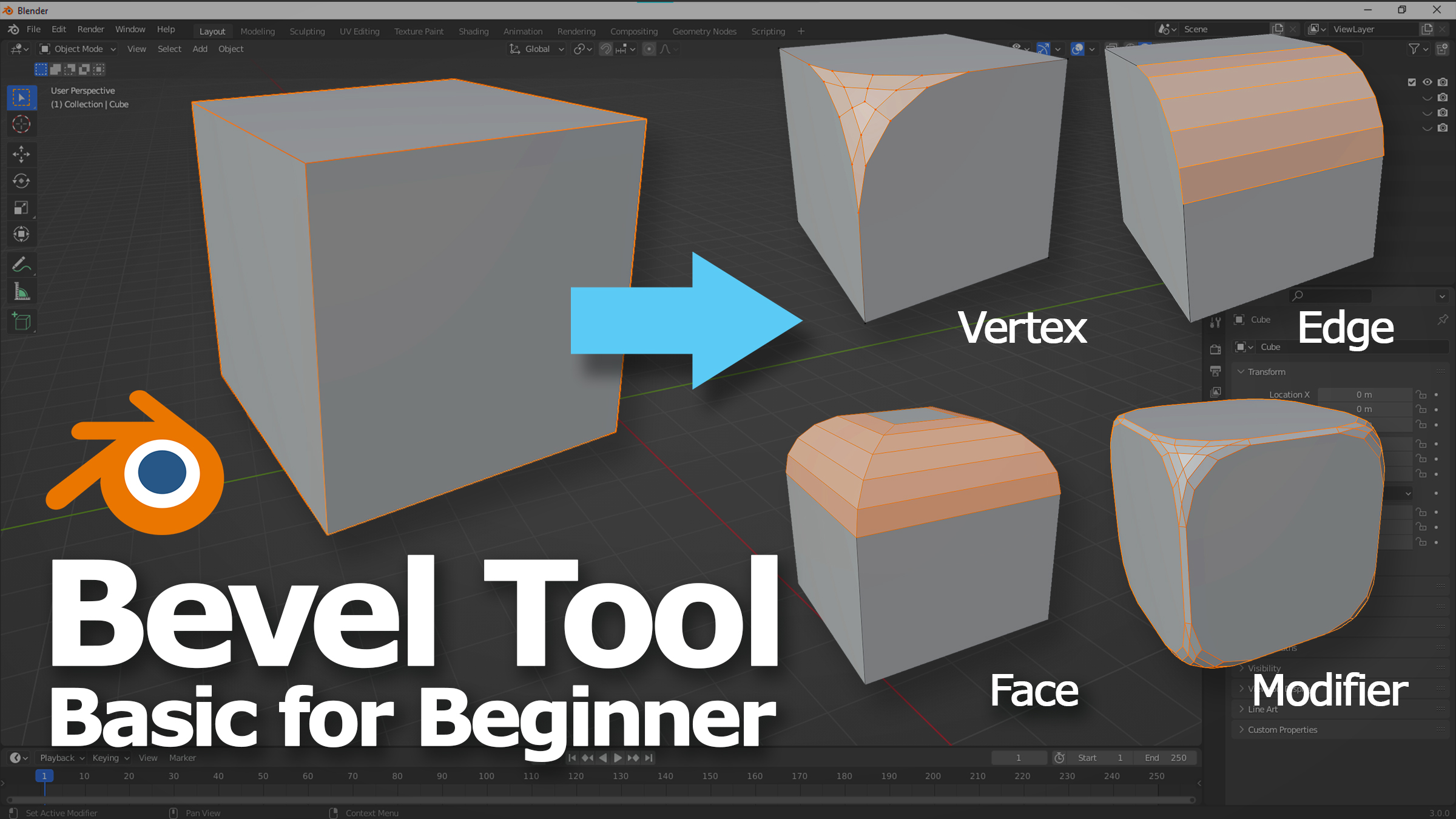
|
|
Fig 3.1 Examples of bevel types Source: https://cgian.com/2022/05/how-to-use-blender-bevel-tool-and-modifier |
Used to smooth sharp corners to give the object a rounded corner appearance.
Go to edit mode
and in the viewport menu, go to edge > bevel edges. Move your mouse to
see the bevel and
scroll the middle mouse button to subdivide more into more rounded
shape.
Week 6 / Hard Surface Modeling
In deciding number of segments for cylinders, always think in addition of
fours, the minimum amount of segment is 8.
Planning for symmetrical modeling
Boolean tool
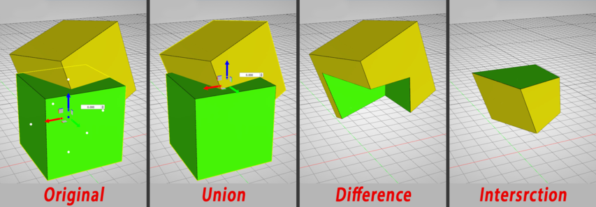
|
|
Fig 4.1 Different modes of Boolean Source: https://www.simlab-soft.com/3d-products/docs/help/10/composer/English/boolean_operations_group_print.html |
The Boolean method is creating different shapes from two intersecting
shapes through difference, union, intersection and slice. Boolean method
can be applied using the bool tool in the Blender add-ons, or using
modifier.
- Union: joins two intersecting objects as one object
- Difference: removes the object and the intersection point, creating a gap. The last object to be selected will be retained
- Intersection: only leaves the intersection point
- Slice: similar to difference but the intersection point is kept and can be moved separately from the main object
Auto Boolean is a destructive method while bursh Boolean is a
non-destructive method. Brush Boolean apply the effect as a modifier
instead.
Make sure that one object is larger than the other object and completely
intersecting to use Boolean tool.
Eliminate n-gon in Boolean
Select 2 opposite vertices and connect them to form quads by going to
viewport menu > vertex > connect vertex path, shortcut key is
J
Another way to create a hole other than Boolean is to scale a cylinder and
delete all the faces until there's one face left, and then inset the face
and delete the insetted face, and then extrude
Instructions
Exercise 1: Modeling from primitives objects
For our first exercise, we are tasked think of any objects that can be
simplified as a combination of primitive shapes and model them in Blender. We
are required to apply shading using the viewport shader and compose the scene
in the camera to output it as a 1280px x 720px PNG image.
Visual reference

|
|
Fig 1.1 Visual reference #1 Source: https://www.pixtastock.com/illustration/74436028 |

|
|
Fig 1.2 Visual reference #2 Source: https://www.researchgate.net/figure/A-sandglass-used-for-timing-a-one-hour-interval_fig4_252061612 |

|
|
Fig 1.3 Visual reference #3 Source: https://www.pixtastock.com/illustration/71097902 |
Since I thought we had to finish this in class the day we were briefed with
the exercise, I went to a random object generator website to get some ideas and one of the things it suggested me is a sandglass.
I thought that's doable in a short time so I just went with it (I did continue
to make the model more interesting by adding details later on after class).
Before I start to model the object, I went to search for some image references
on the structure and details I can add to a sandglass model.
Modeling process

|
| Fig 2.1 First attempt at modeling - perspective view |

|
| Fig 2.2 First attempt at modeling - perspective top view |
I started with using two cones as the glass of the sandglass, cylinders for the base, cover, poles and metal gold rings. The sphere is there to add some details to the poles and the same goes to the smaller squashed cylinder at the top of the sandglass as well.
Further development of modeling
Fig 3.1 Video showcasing the further detailed model

|
| Fig 3.2 Further detailed model - Perspective view |

|
| Fig 3.3 Close up of sand falling down structure using cone and cylinder |

|
| Fig 3.4 Further detailed model - Top perspective view |
Then, I added some more detailing to the sandglass model with the gold
material with reference to the image references. The sand in the glass is also
made with two cones with different scaling, though for the part where the sand
is falling down, it's made with a cone at the top and continued with a
cylinder which goes through the bottom pile of sand. The base and cover of the
sandglass is modeled to have a oblong shape rather than a perfect circle to
give some stylisation to the design. The, glass, wooden base and cover of the
sandglass is shaded smooth to remove the edges.

|
| Fig 3.5 Scene setup using planes |

|
| Fig 3.6 Scene setup using planes (without wireframe) |
After that, I used two planes to create a dark blue backdrop as the setup for
the render scene. Dark blue is used as it contrasts with the colours of the
sandglass, thus drawing the attention to the sandglass more and accentuates
the shine on the gold metal material.

|
| Fig 3.7 Properties of the material used |

|
| Fig 3.8 Settings of the viewport shader |
As for the material choice for the shapes, the gold metal look is created by
increasing the metallic slider, the glass look is created by decreasing the
alpha slider for transparency and decreasing the roughness slider for the
smooth, reflective look. Metallic slider is increased a bit to give it a bit
more shine. The materials for the base and the poles are set with varnished
wood in mind, and the roughness slider for the sand material is increased to
give it a matte look.
For the viewport shading, rim light preset is used to give the sandglass a
grand look and the lighting direction is adjusted very far to the back to make
the shine on the gold metals more prominent. Backface Culling is enabled to
give shading transparency to the glass material, and the outline is in dark
red to give some subtle sense of volume to the objects. Other properties are
adjusted to control the brightness of the scene. The scene is later composed
according to the rules of thirds and exported as PNG image for
submission.
Final primitive object model

|
| Fig 4.1 Final sandglass model |
Exercise 2: Non-destructive modeling
For this exercise, we are tasked to refer to animal drawings that show the
basic form construction of the animal in primitive shapes. Then, we are to
model the animal based on the drawing using primitive shapes and
non-destructive modeling tools such as subdivision surface, array, curve,
simple deform and lattice in Blender. The final model would need to be
assigned basic materials, composed in the camera and output as image for
submission.
Visual reference

|
|
Fig 5.1 Main image reference Source: https://drawpaint.art/dogs/ |

|
|
Fig 5.2 Additional image reference (dog drawing) Source: http://conceptdesignacad.blogspot.com/2012/05/animal-anatomy-with-jonathan-kuo-1-spot.html?m=1 |
|
|
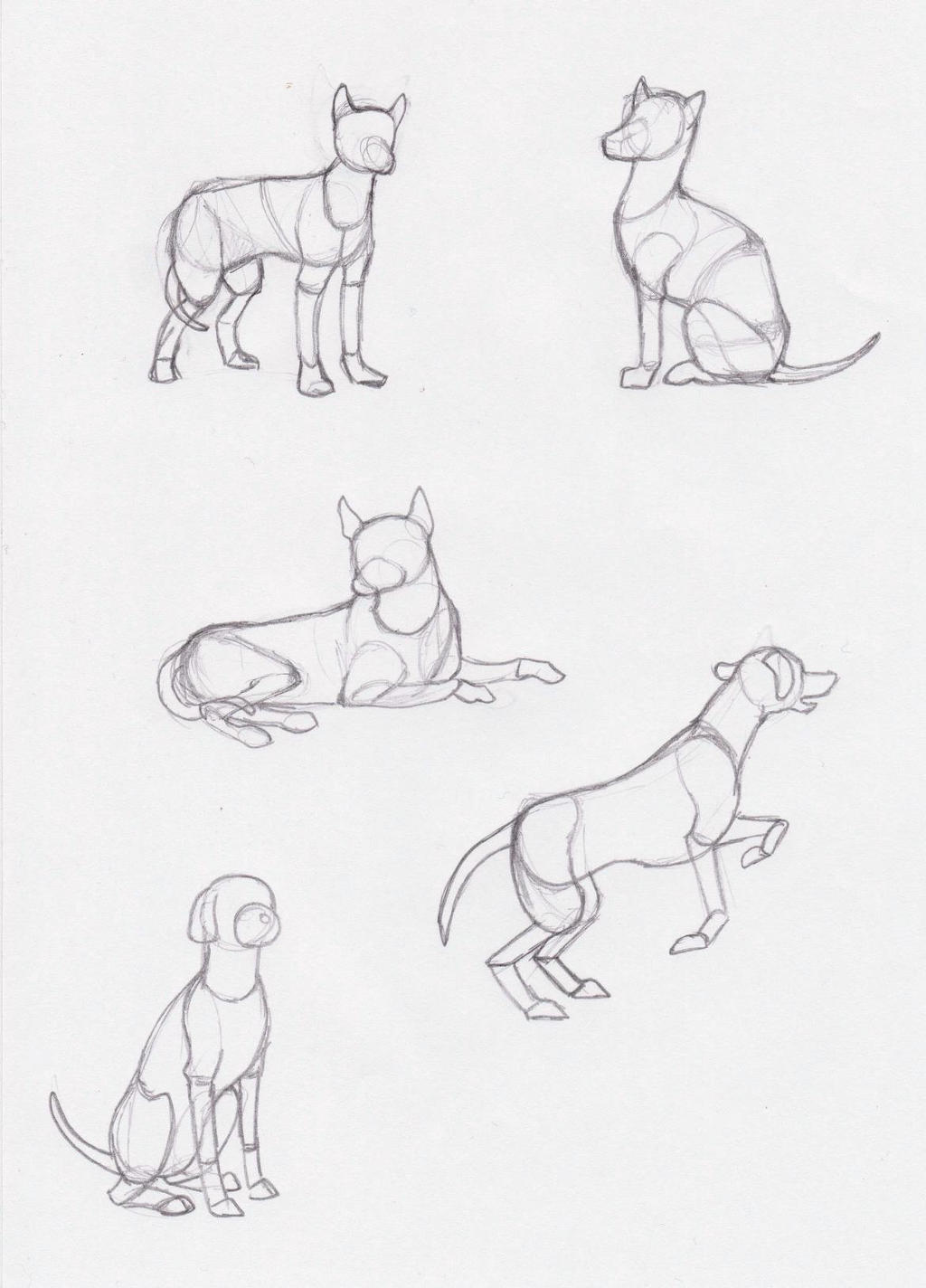
Fig 5.3 Additional image reference Source: https://www.deviantart.com/seadre/art/Sketch-dog-358922101 |
The animal that I chose to model for this exercise is a dog. Fig 5.1 would be
my main reference throughout creating the model, while the additional
references are for me to refer to different angles and shape construction of
the dog, since Fig 5.1 just shows it at one angle. Fig 5.3 is mainly used to
reference the tail and ears.
Modeling process

|
| Fig 5.4 Blocking out the shapes and pose |
I first started with roughly blocking out the form of the dog using shapes, modifiers and lattices, so that I can get a sense of its proportion and it would be easier to refine the model later on. Mainly cubes are used for the model, except for the neck, joints and legs, which are made of cylinders and spheres.

|
| Fig 5.5 Modeling the tail |
Then, I proceeded to model the tail using bezier curve and a cube with array and curve modifiers. Subdivision surface modifier is also added to the cube with a level of 3 so that the tail would look smoother. The radius of the bezier curve is late adjusted in edit mode using the radius slider in the objects property sidebar so that the tail would go from thick to thin.

|
| Fig 5.6 Modeling the ears |
I also added ears to the model so that it would resemble a dog more clearly. The ears are made using a cube with the subdivision surface, taper and stretch modifier added. The scale of the cube is adjusted while using the modifier so that it would form a triangular shape cuboid.

|
| Fig 5.7 Modeling the paws |

|
| Fig 5.8 Adjusting the shape of the paw in edit mode |
For the paws, they are modelled from a cube with multiple simple deform
modifiers added. The cube is first subdivided using the subdivision surface
modifier, and then tapered and stretched with a restriction to the Z axis so
that it won't stretch vertically. The scale of the cube is adjusted as well to
match the shape of a paw. The vertices of the cube is also adjusted in edit
mode to make the front face more slanted without affecting the other
parts.

|
| Fig 5.9 Lattice object for head and mid-section of body |
The shape of the head was first modeled using stretch modifier and the body is
modeled using a combination of stretch and taper modifier, and then both are
fine tuned using lattice. For all the other parts of the body, a combination
of stretch and taper simple modifiers were used to create the needed shape,
and the vertices of the objects were later fine tuned in edit mode to make the
shape more accurate. Though, the front section of the body is done only by
adjusting scaling of the cube and its vertices in edit mode. The thigh of the
model on the other hand, is created using a cube with subdivision surface
modifier in Catmull-Clark option with 2 levels, and with scaling
adjustments.

|
| Fig 5.10 Refined tail shape |
The shape of the tail is later refined as well to match the model.
Fig 6.1 Video showcase of model
with and without material and wireframe

|
| Fig 6.2 Still images of model in different views |

|
|
Fig 6.3 Settings of materials used in the model |

|
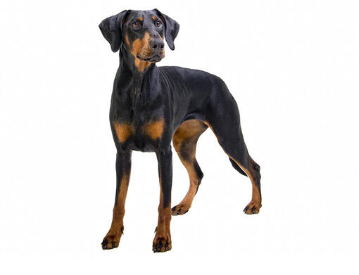
|
Fig 6.4 Model colour reference Source: http://www.vetstreet.com/dogs/doberman-pinscher |
After finishing with modeling the dog, I then assigned materials to the model. The colours are chosen based on the Dobermann dog breed colours (Fig 6.4), as I thought the form of the model kind of suits the look of the breed. The materials setting are assigned with the model being a toy dog in mind, made of brown metals and dark brown wood.

|
| Fig 6.5 Scene setup |

|
| Fig 6.6 Camera composition |

|
| Fig 6.7 Viewport shading settings |
I then used two planes to create a scene with the colours chosen to look like
an outdoor setting. The outdoor.sl lighting setup preset is chosen as well to
create a outdoor looking scene. I composed the model at a low angle as it
seems more interesting and make the composition look less flat. I align the
dog's head to the center line of the camera to create a focal point on that
spot.

|
| Fig 6.8 First attempt of dog model |
 |
| Fig 6.9 Reference picture |
After receiving feedbacks from Mr. Kamal, I resized the front legs to be a bit bigger to make the proportions better. I also searched for a reference picture to refer to the size of the legs.
Final non-destructive modeling model
 |
| Fig 7.1 Final non-destructive modeling dog model (updated) |
Exercise 3: Modeling from cylindrical shape
For this exercise, we were tasked to model any different objects made of
cylindrical shape using tool such as extrude, loop cut, bevel and inset. After
that, we need to compose the objects in a scene and render it with light and
shadow using viewport shading, and export the render image in 1280px x 720px
resolution.
Visual reference
Fig 8.1 Reference images used and source link
I started with finding reference images of the objects that I want to model
for this exercise to use as blueprints for my modelling. I tried to find
different shaped cylindrical objects to give variety to the composition. The
Coca-Cola bottle picture was given by Mr. Kamal for our in-class
activity.
Modeling process

|
| Fig 9.1 Modeling Coca-Cola bottle following the reference image |

|
| Fig 9.2 Modeling the other objects following the reference images |

|
| Fig 9.3 Modeling the plate using reference image as visual guide |

|
| Fig 9.4 Bowl modelling from in-class activity |
The Coca-Cola bottle, glass mug, champagne bottle and glass, and vase were modeled directly following the reference image. Since the reference image for the plate is in perspective, the plate was first modeled directly following the image and then further adjusted and resized to make it look more like a plate in all angles using the image as a visual reference only. All of the objects were modeled from a cylinder with 12 segments (except for the glass mug) mainly using loop cut, extrusion and inset for the base. For the Coca-Cola bottle and the champagne bottle, the bottle cap and gold tin foil were modeled separately from the body of the bottle.
The models were then shaded smooth and subdivision surface is applied to
make the model look smoother. The subdivision surface setting was changed
between using Catmull-Clark and simple depending if the model needs more
edges details or a rounded smooth detail. Solidify modifier is also applied
to plate, vase and champagne glass to give the models a thicker
appearance.
An additional bowl was made for an activity in-class by cutting the sphere
in half. The base of the sphere is then moved upwards to create a flat base
by selecting multiple loop cuts and transforming them. The thickness of the
bowl is done through a destructive method by selecting all the faces on the
surface of the bowl and extruding them by clicking faces > extrude faces
along normal in the viewport menu.
Details of modeling glass mug

|
| Fig 10.1 Basic form of glass mug using cylinder with 8 segments |

|
| Fig 10.2 Applied 1 level of subdivision surface to create more vertices |

|
| Fig 10.3 Creating the pattern groove on the glass mug using inset |
The glass mug was done with a bit more detail than the other models. I
started with modeling the glass mug by directly following the reference
image using a cylinder with 8 segments, loop cuts and extrusion. After the
basic form of the glass mug is modeled, subdivision surface modifier was
applied to the model to create more vertices and the indented groove pattern
along the glass mug was created by selecting a row of faces at once and
identing them. The handle of the glass mug is done by selecting faces at the
side of the model and extruding them while applying the necessary
transformation. The end of the handle is joined to the bottom part of the
glass mug by selecting the faces that needs to be joined and using bridge
edge loop by pressing F3 on the keyboard.
Composing the objects

|
| Fig 11.1 Resizing the object to correct proportions |

|
| Fig 11.2 Composing the objects according to rules of thirds and center lines |

|
| Fig 11.3 Applying materials and setting the scene of the composition |

|
| Fig 11.4 Materials settings for the objects |

|
| Fig 11.5 Viewport shading settings |
After finishing with modeling the objects, I then put all the objects in a
line on the same axis and resized them until their proportions make sense.
After that, I arranged them on a plane by moving them around to create a
composition. Different materials are then applied and light and shadow of
the viewport shading is then adjusted. The studio light preset was used for
the shading.

|
| Fig 12.1 First attempt of render |
After receiving feedbacks from Mr Kamal, I went to apply Catmull-Clark subdivision surface modifier to the coke bottle, the champagne gold foil and the bowl to give them a smoother appearance without the visible lines.
Final modeling from cylindrical shape models

|
| Fig 12.1 Final cylindrical shape models (updated) |
Exercise 4: Modeling a Karambit
For this exercise, we were given a reference image of a Karambit and were
tasked to model it using the hard surface techniques tool that we've learned.
The final output should be rendered in 1280px x 720px resolution with viewport
shading settings.
Modeling process

|
| Fig 13.1 Given reference image |

|
| Fig 13.2 Base form of the model |

|
| Fig 13.3 Creating hard surface details using knife tool |
I created the model starting from top to bottom using a hollowed out cylinder. The hollowed out cylinder was created by scaling the cylinder to the needed size and thickness, and remove all the faces until there's one front face remaining, then using inset to match the size of the loop and delete the inset face. Thickness is then added again by extruding the faces. The rest of the knife is then modeled by adding loop cuts and arranging the wireframes. After the base form of the Karambit is modeled, more vertices are added to create the hard surface details by using the knife tool.

|
| Fig 13.4 Duplicating a part of the knife for the handle |

|
| Fig 13.5 Reshaping the duplicated part to match the shape of the handle |

|
| Fig 13.6 Adding hard surface texture details using knife and adjusting vertices |
I then proceeded to model the handle of the Karambit. To make things quicker,
I duplicated the original model to extract the the handle part of the knife
since its shape is similar to the actual handle. The extracted part is then
reshaped according to the reference image to match the shape of the handle. As
the handle in the image has an uneven surface texture, I tried to reproduce it
on the model of the handle by adding more vertices using knife tool and
adjusting the position and scale of the vertices to create the texture
following the reference image.

|
| Fig 13.7 Placing spheres in screw area and using cubes to create the gap |

|
| Fig 13.8 Close up of the screws with material |

|
| Fig 13.9 Viewport shading and material settings |
Fig 13.10 Video showcase of finished model
with wireframe, solid mode, and with material
After that, spheres were used as the screws in the handle. The hole for the
screws were made by using the difference brush boolean function between a
sphere and a handle. The screw is a smaller scale of the same spheres used and
the screw gaps were also created using the difference brush boolean function
between cuboids and the spheres. Some tweaks were made on the vertices of the
edge of the knife and the surface texture of the handle so that their surface
look more hard and their topology doesn't look weird.

|
| Fig 13.11 Setting the scene using a plane |

|
| Fig 13.12 Composing the Karambit |
Next, I used a plane which is positioned close to the Karambit to reduce the
harsh shadow made on the plane, and to make it look like it's laying on a wall
or table. As shown in Fig 13.9, the outdoor lighting preset is used as it
gives the scene a brighter look, and also the light source shines from the
top. The scene is composed with the camera centerline in mind.

|
| Fig 13.13 First attempt at Karambit model |
After receiving feedbacks from Mr. Kamal, I added a subdivision surface modifier using the simple option at a value of 1 for level views.
Final Karambit model
 |
| Fig 14.1 Final Karambit model (updated) |
Feedbacks
Week 11
Exercise 1 is good. For exercise 2, the proportion of the front legs kind of looks a bit unnatural, maybe they need to be a bit bigger, can find more reference pictures to refer to. But silhouette wise it looks good. In exercise 3, the coke bottle, champagne tin foil and bowl have vertical lines in the render that may be because of a problem of subdivision. So maybe check it as the surface should look smooth.
The glass is good. As for exercise 4, the black part of the handle seems to look weird, but in terms of silhouette it looks good.
Reflection
The exercises definitely helped me in understanding how to use the tools in Blender a lot, and also gave me a chance to learn on how to compose an object/scene in different ways using different lightings. The most challenging exercise is definitely exercise 4 as I've never modeled hard surface before (the most I did was cylindrical objects as I've watched a YouTube tutorial video way back when). I had to fumble around to understand the process and get it right, but once I'm familiar with it, it gets easier to figure how to to use it and is especially helpful going into project 1.
mamma mia! ur karambit looks so sharp!
ReplyDelete